Exploration Robot
Designed by
Sizhe Gao(sg2267), Ziyuan Lin(zl647)
Demonstration Video
Introduction
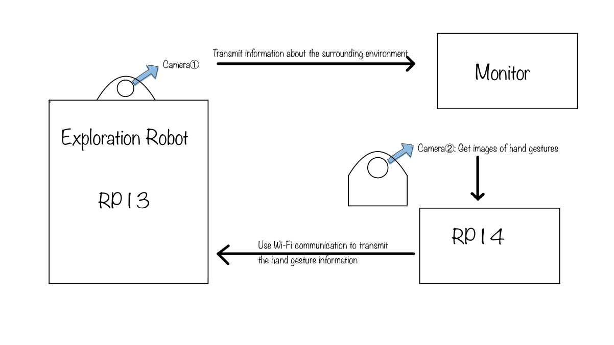
People are very vulnerable to danger and accidents when exploring uncharted areas, be it abandoned tunnels or unknown caves. Therefore, The purpose of our robot is to explore the way for humans under the unknow or danger environment. In our project, two cameras will be installed in our project. One will be placed on our robot to record the view and send it back to the monitor simultaneously. Additionally, RPi 3 will be applied to control movement of the Robot. The other one will be used to analyze our hand gestures and give commands to the robot (forward, left, right, stop). The hand gesture recognition will be based on Computer Vision, and we will apply one more RPi 4 to handle the recognition.
Project Objective:
- Raspberry Pi camera configure and control
- Robot Control
- OpenCV and Mediapipe
- Hand gesture recognition
- Socket Communication includes UDP and TCP protocols
- Standard Servo configure
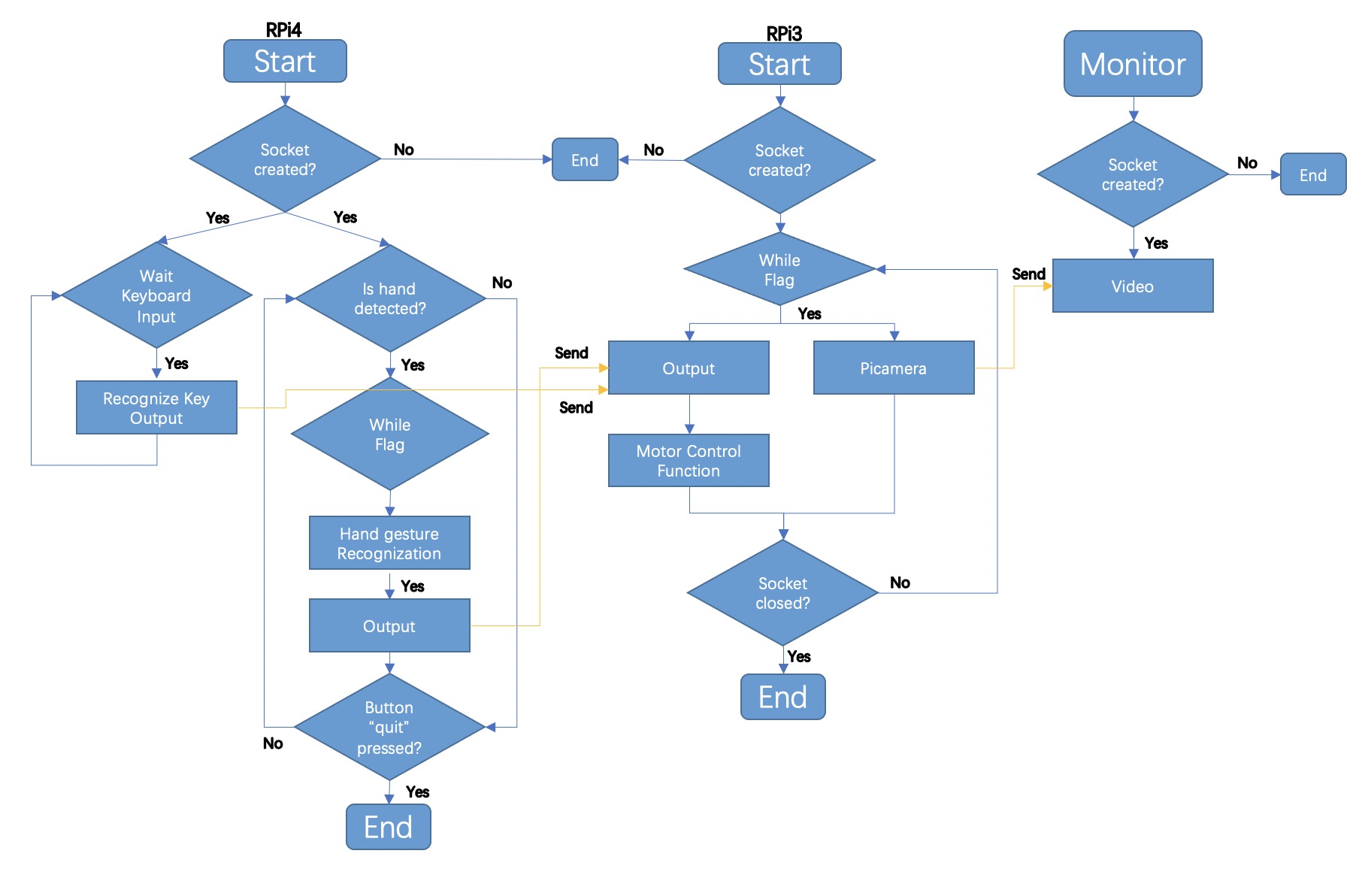
The general idea is that when picamera in RPi4 recogizes the relevant gesture, the signal will be sent using UDP protocol to RPi3 which is in the Robot, and RPi 3 will control the robot's movement by giving it the appropriate commands based on the signals received. In addition, RPI4 can also send keyboard input to control the rotation of the camera on the robot, which allows us to observe the robot's immediate environment.
Design
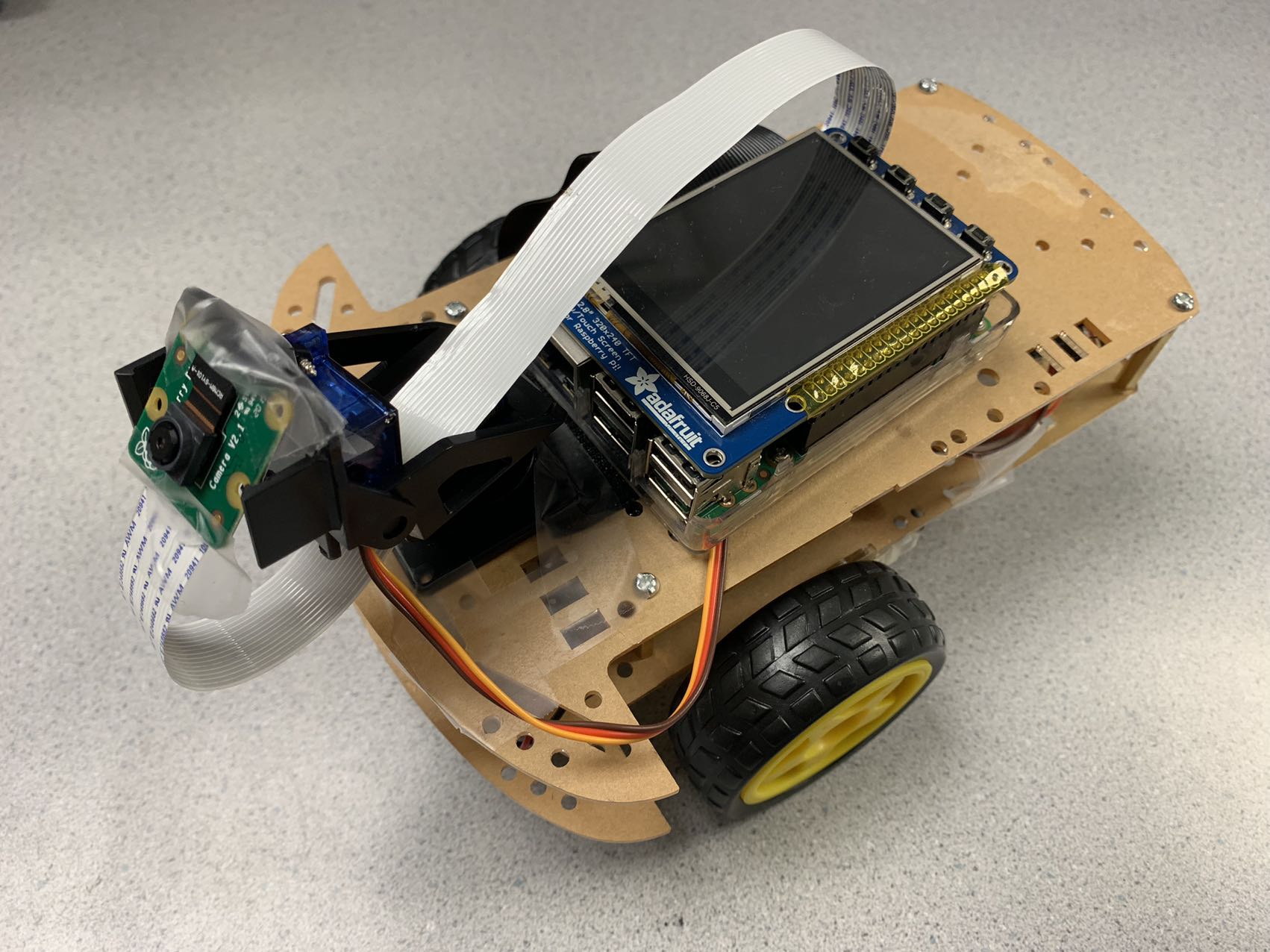
The hardware design of our Exploration Robot consists of two Raspberry Pi, two picamera, four motors, and a modeling robot. We first started with assembling the robot included a RPi, a picamera, two motors, and Mini Pan-Tilt Kit assembled with two micro servos which used to control the direction of picamera rotation.
For the picamera, we need to connect it with RPi3 using a cable.
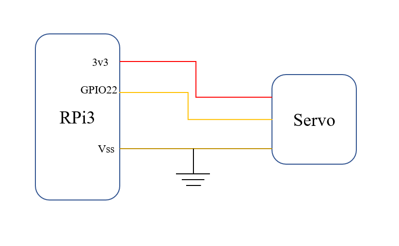
When it comes to the Mini Pan-Tilt Kit, we used Adafruit1967, which can provide us a perfect way to give the picamera full range motion. The angle of rotation of the Pan-Tilt is about 100° from left to right, as well as approximately 150° from top to bottom. Besides, the type of two micro servos is SG-92. First of all, we combined the pan tilt and the two servos together following the guidance. And then, connected the pin portion of two servos with RPi3 respectively. Among three pins of each servo, the brown one needs to be grounded. The red one is connected to the power supply (3V3 output on RPi3). And the yellow one should be connected to GPIO to provide the control signal. GPIO 13 and GPIO 22 are selected for each servo separately. The circuit shows as below (using GPIO22 as output to control the servo):
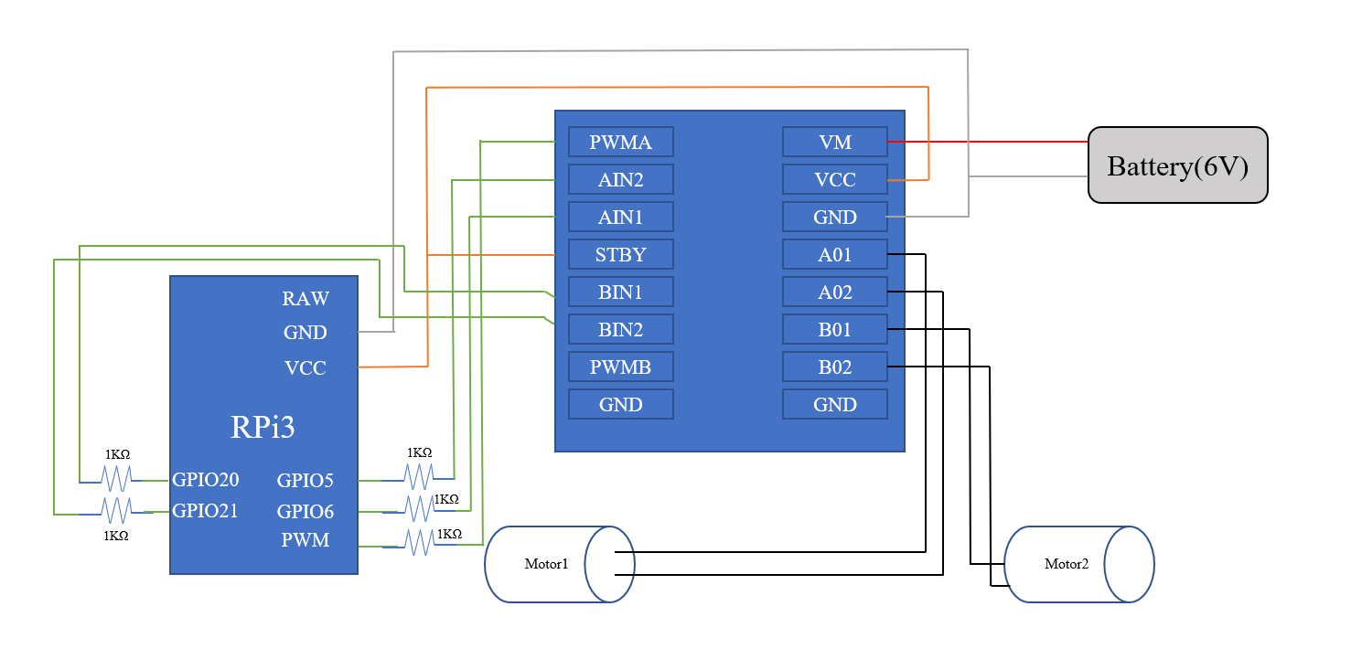
After completing the connection of servos, we tried to connect DC motors and motor controller with Raspberry Pi. GPIO Pins 5 and 6 are connected to AIN1 and AIN2, used for direction control, while GPIO 20 and 21 are used for direction control and connect to BI1 and BI2 on the MC. GPIO 16 is connected to PWMB which is used for speed control. Besides, 3.3 Volts from RPi is connected to motor controller VCC and 6 Volts from battery is connected to VM, voltage for the DC motor. Also, 1K current limiting resistors are used to protect GPIO pins. And all the devices need to be grounded. The circuit shows as below:
The other part of the project is hand gesture recognition, which includes a RPi4 and a picamera. The only thing we need to do is connecting them together using a cable with suitable length.
1) Picamera for Image Capture
After two Picameras were assembled in the RPi3 and RPi4 respectively, we used sudo raspi-config to activate the camera in Pi, and then
we could write the python code to control the picameras. There are two ways we used to control them.
First, we import cv2 package for capturing the images, which we used for implementing the function of hand gesture recognition.
    import cv2
    #Use CV2 to capture video
    cap = cv2.VideoCapture(0)
The second way is to import the PiCamera library, which we also can capture the image. Additionally, we could modify more settings in the camera such as resolution, framerate and so on.
We used this method in the picamera of robot.
    import picamera
    with picamera.PiCamera() as camera:
      camera.resolution = (640, 480)      # pi camera resolution
      camera.framerate = 15               # 15 frames/sec
      time.sleep(2)                       # give 2 secs for camera to initilize
2) Mediapipe for Hand Gesture Recognition
MediaPipe is a multimedia machine learning model application framework developed and open-sourced by Google Research,
which can directly call its API to complete target detection, face detection and key point detection.
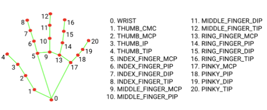
Here we use the 21 keypoints detection function for the hand. Firstly, we need to install and import the mediapipe in the Pi.
pip install mediapipe
Then, we could call the functions in the mediapipe library to create the hand detection model to infer the 21 3D landmarks of a hand from a single frame. Here is the code to implement the above function and the gesture coordinates below.
    # Hand Gesture
    drawingModule = mediapipe.solutions.drawing_utils
    handsModule = mediapipe.solutions.hands
After creating the hand gesture model and obtaining the cordinates of hand via mediapipe, we could design our algorithm to determine different gestures and send different messages to achieve the purpose of controlling the robot.
3) Algorithm for recognition to control the Robot
First of all, we use the handLandmarks object to extract the coordinates of specific points on the hand,
such as the top and bottom of the hand and the thumb and little finger.
And then, we use gestures to achieve the functions of forward, left turn, right turn and stop;
the first three functions will be judged by the angle between the index finger and the y-axis coordinates,
while the stop function will be judged by the difference between the thumb and the little thumb coordinates.
If the hand is making a stop gesture, it sets the stop_sign variable to 1 and outputs "STOP". Otherwise, it checks if the hand is making a forward, right,
or left gesture and outputs the corresponding command. If the hand is not making any of these gestures, it outputs "FORWARD".
Detailed steps to algorithm can be explained using the pseudo code below:
    for each point in the hand landmarks:
      calculate the pixel coordinates of the point
      if detect the points we need to use in the hand:
        store the coordinates in different variables separately

    if the top and bottom coordinates are both available:
      calculate the difference in x and y coordinates
      calculate the angle of the hand using the differences in x and y coordinates

      if the thumb and little finger coordinates are both available:
        calculate the difference in x and y coordinates between the thumb and little finger coordinates
        if the difference in x and y coordinates is small:
          set the stop_sign variable to 1
            output "STOP"
        otherwise:
          set the stop_sign variable to 0

      if the stop_sign variable is 0:
        if the angle of the hand is less than 45 degrees and the difference in x coordinates is negative:
          output "RIGHT"
        else if the angle of the hand is greater than -45 degrees and the difference in x coordinates is positive:
          output "LEFT"
        otherwise:
          output "FORWARD"
4) Servos Control
In order to achieve the rotation of the picamera orientation, we need to install it in the Mini Pan-Kilt. And
we need to connect the two servo's contained in the pan kilt to the RPi3 and write code to control them.
First of all, we import the Servo class from the gpiozero library in Python.
This class allows us to control a servo motor, which is a type of motor that can rotate to a specific angle.
The detailed code is shown below:
    from gpiozero import Servo
    servo = Servo(13)
    servo_2 = Servo(22)
In this code, we created two instances of the Servo class and assigned them to the variables servo and servo_2. The Servo class takes a single parameter, which specifies the GPIO pin that the servo is connected to. In this case, the first servo is connected to GPIO pin 13, and the second servo is connected to GPIO pin 22. We transfer the information typed by the keyboard to the Raspberry Pi through a socket (which will be described in the next section), which is controlled by the above code.
5) Socket for Wi-Fi Communication
In this project, we chose wifi communication to enable data transmission and reception between two Raspberry Pi's, and between Raspberry Pi and laptop. The reason why we chose it from three aspects:
- Convenience: WiFi allows devices to connect to the internet without the need for physical cables, making it more convenient than wired networks.
- Mobility: WiFi allows devices to connect to the internet wirelessly, so users can access the internet on the go and move around freely without losing their connection.
- Performance: WiFi networks can provide high-speed internet access, making them suitable for applications that require fast data transfer rates, such as streaming video and audio.
Wi-Fi communication relies on sockets to establish connections and transmit data over a network.
A socket is a software interface that allows applications to communicate over a network, such as the internet.
Sockets use various network protocols, such as TCP (Transmission Control Protocol) and UDP, to transmit data between devices.
In our project, we use UDP protocol to transmit the data of hand gesture from RPi4 to RPi3.
Firstly, the socket library is imported and initilized. The code of sender is shown below:
    from socket import *

    udp = socket(AF_INET, SOCK_DGRAM)
    targetAddr = ("10.49.71.170", 8080)
    udp.bind(("", 3000))
The targetAddr variable is set to a tuple containing
the IP address "10.49.71.170" and the port 8080.
This indicates that the socket will be sending data to the specified IP address on port 8080. When we get the data needed sending,
we could use the code below to achieve the send function.
udp.sendto(data.encode("utf-8"), targetAddr)
Using the UDP protocol, the implementation of the receiver side is also very simple, we just need to initialize the UDP and bind the same port as the receiver side,
and then use the recvfrom() method to receive the message from the port.The code of reciever is shown below:
msg,addrInfo = udp.recvfrom(1024)
We put the information obtained by gesture recognition and keyboard typing in a list during the transfer and thus transfer it simultaneously,
which allows us to reduce the number of servers and speed up the transfer efficiency.
This means that we need to use the json.dumps() function to convert the data type to JSON string before using the sendto function, which allows the data to be transmitted over a network in the form of a list,
6) Logic Flow Chart for whole system
Testing&Result
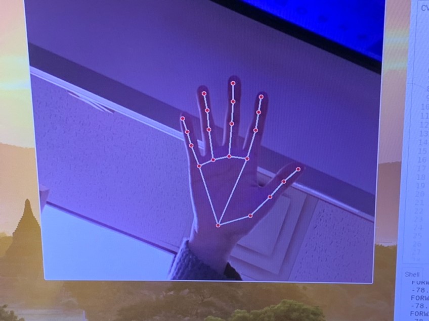
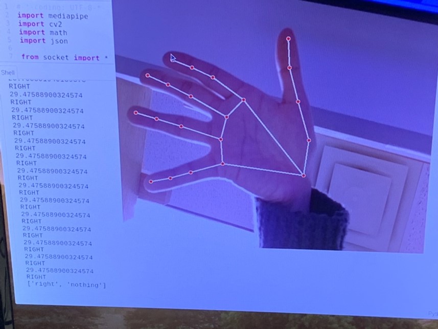
We first tested the mediapipe to check if it could recognize our hands under most of background, which should not be affected by light or color a lot. The output demonstrated great as the figure below. The detection was quick and correct, and it did not have higher demands of the background.
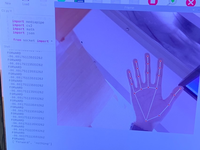
The second part of testing was to recognize our hand gestures. We initially calculated the distance between the top and bottom of the index finger to determine which direction our hand was pointed at and sent the output to Rpi of car. While we test, we figured out that it was not stable and always outputted the result we expected. It would have higher accuracy if we moved hands closer to camera, however, if we move further, it could always detect forward since the distance between two points became smaller. Instead of comparing distance, e switched to use the method of determining angles. We still applied the coordinates of the two points of index finger but subtracting to get the distance of x direction and y direction, then used the tangent method to calculate the angle between index finger and x-axis. After testing, no matter how close or far from the camera, the output was as the expected. The figure demonstrated the printed output with different hand gestures (The figured were mirrored).
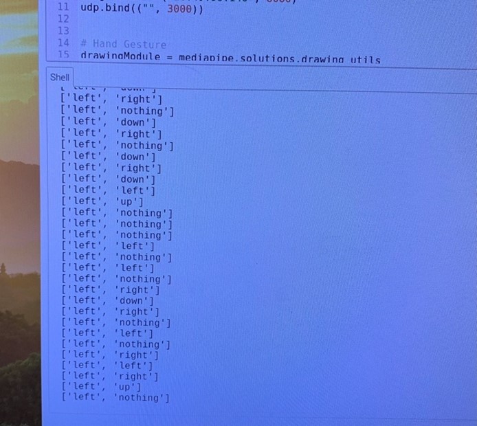
As we needed to send the output of hand gesture to our RPi on car, we tried to use socket with TCP communication. However, the delay was around five to six seconds to send an output. Then we changed to use the UDP communication which was also supported with socket. The UDP was simple. The sending speed was faster, and delay was around 0.5 seconds. For sending the control of servo, we wanted to use the keyboard of laptop to send the signals. We used the input() method of python to wait for the input from keyboard, but the program would stop to wait for input and we had to hit enter key every time. We used the cv2 waitkey function to wait the key input and it wouldn’t interrupt the other processing. And it did not require to hit enter to confirm, but directly receive the input. To send the control signal of both hand gestures and servo keyboard inputs, we modified the encode type of servo as json, so that it could send as an array as the figure below.
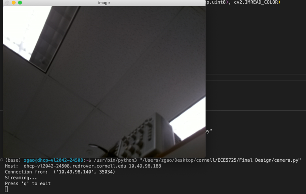
To stream the video from camera of car back to our laptop, we created another socket which was mainly used as connecting with pi camera. We used TCP socket, there was around one second delay to transmit the video back. We did not set a static IP, and it required as to modify the address every time.
Note: Information about the robot part of the test is available in the video above.
Conclusion:
Our final design could control the car moving forward, turn right, turn left, and stop with hand gestures. The keyboard connected to RPi4 could control the servo to move up, down, left, and right. The camera of RPi3 on car could stream the video back to our laptop with low delays.
Future Work
If we had more time to continue working on this exploratory robot project, one of the first features we would want to expand is the precise linear motion of the robot. Since the two continuously rotating servos are not identical, it is almost impossible to make the robot move linearly without any error. Therefore, it is better and more convenient to use a wire reader to achieve it.
Additionally, we could design a stand with a housing and print it out using 3D printing technology, then assemble it with the RPi4 and Picamera to get a more aesthetically pleasing gesture recognition device.
Eventually we should try to find a lower latency transmission strategy, as we found that there is still a relatively large latency in the video, which may make it difficult to make timely feedback actions when we manipulate remotely, only through the robot's camera.
Work Distribution
Sizhe Gao
sg2267@cornell.edu
Worked on the building the robot, configuring the hand gesture recognition, algorithm of gesture judgement, servo control, and socket programming.
Ziyuan Lin
zl647@cornell.edu
Worked on the building the robot, configuring the mediapipe, algorithm of gesture judgement, motro control, and socket programming.
Parts List
| Components | Cost | Number | Total Cost |
|---|---|---|---|
| Raspberry Pi Model 4B | 1 | Provided in Lab | |
| Raspberry Pi Model 3 B+ | 1 | Provided in Lab | |
| PiCamera | 2 | Provided in Lab | |
| Motor Contro | 1 | Provided in Lab | |
| Mini Pan-Kilt | 1 | Provided in Lab | |
| Servos, Resistors and Wires | Provided in lab | ||
| Final Cost | $0 |
References
[1] PiCamera Document[2] Tower Pro Servo Datasheet
[3] OpenCV2 Document
[4] Mediapipe
[5] Video Streaming
[6] Pigpio Library
[7] R-Pi GPIO Document
[8] Mini Pan-Tilt Kit
[9] Socket
[10] Bootstrap